Reasons for choosing our testing services
ZHONGXI Testing has obtained inspection qualification certifications from multiple countries and regions worldwide. We possess a senior testing team and advanced testing methods, providing independent, impartial, and professional third-party verification services for global carbon projects.

Internationally recognized authority
Certified by multiple international standards such as CNAS, VCS, and GS, with reports universally applicable worldwide.

Global service capability
Covering 140+ countries and regions, it supports on-site detection and remote verification in multiple languages.

Professional experimental methods
Adopt standard experimental methods to ensure accurate and reliable data.
Dual-Stage Hall Thruster Coupled Magnetic Field Diagnostics: Precision Mapping for Next-Generation Electric Propulsion
The dual-stage Hall thruster represents a paradigm shift in electric propulsion, decoupling plasma ionisation from acceleration via two distinct magnetic-field regions. However, the coupled magnetic topology—where the inner and outer stage fields interact nonlinearly—determines the thrust efficiency, plume divergence, and erosion patterns. Unlike single-stage devices, the coupled field requires vectorial, time-resolved characterisation of both the steady-state B-field and the high-frequency oscillatory components that drive anomalous electron transport. Our testing service is exclusively designed to resolve these complex interactions, providing a complete 3D magnetic map with sub-millimetre spatial resolution and sub-nanosecond temporal fidelity, enabling thruster developers to optimise field shaping, minimise wall losses, and predict lifetime with unprecedented accuracy.
The Critical Need for Dedicated Coupled-Field Detection
In dual-stage Hall thrusters, the coupling coefficient between the near-anode (ionisation) and the acceleration (main) zones is exquisitely sensitive to magnetic field alignment, gradient curvature, and cross-field diffusion. Standard gaussmeter surveys along a few axial lines are insufficient—they miss the azimuthal asymmetry and field-line connection that govern electron cross-field mobility and the resulting current-voltage characteristics. Moreover, the coupled field often generates breathing-mode instabilities (10–50 kHz) and rotating spokes (1–100 kHz) that modulate the local magnetic field via induced eddy currents in the magnetic circuit. Our detection protocols are tailored to capture both the DC baseline topology and the AC perturbation spectrum, providing a unified dataset that correlates magnetic behaviour with discharge oscillations and plume properties.
Our Comprehensive Detection Capabilities for Coupled Magnetic Fields
We deploy a multi-sensor, fully automated test bench that integrates Hall-effect, magneto-optical, and inductive sensing techniques. The following represent our core high-end offerings:
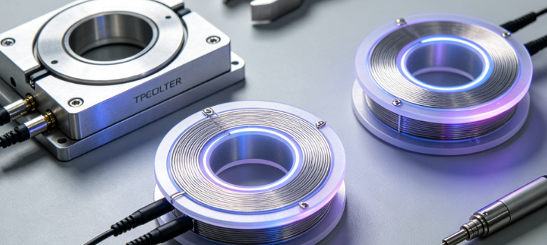
3D Vector Hall Mapping with Sub-Millimetre Resolution: Using an array of 16 miniature Hall sensors (sensitivity 0.01 mT, active area 0.1×0.1 mm²) mounted on a precision 5-axis robotic stage, we scan the entire thruster discharge channel and outer magnetic circuit. The stage provides positional repeatability of ±5 µm and allows arbitrary curvilinear paths following the magnetic flux lines. We reconstruct the full vector field (Bx, By, Bz) over a volume of up to 300×300×200 mm³, generating a grid of over 100,000 measurement points per full scan. This density is sufficient to resolve the magnetic mirror ratio and the field curvature radius with an error margin below 1%, critical for predicting electron confinement.
High-Frequency Magnetic Field Probes (AC Coupling): To capture oscillatory components, we employ custom-built pickup coils (3-axis, 10 turns, 2 mm diameter) with a bandwidth from 10 Hz to 50 MHz, connected to a 16-bit, 100 MS/s digitizer. This system measures the time-varying magnetic field dB/dt simultaneously at multiple spatial positions, enabling us to compute the phase and amplitude distribution of rotating spokes and breathing-mode oscillations. We provide power spectral density (PSD) maps that identify resonant frequencies localised in specific regions of the coupled field, which are directly correlated with the electron cyclotron drift instability.
Magneto-Optical Kerr Effect (MOKE) Imaging for Surface Fields: For near-wall field gradients that affect ion sputtering, we apply wide-field MOKE microscopy with a spatial resolution of 2 µm. This technique visualises the stray field emanating from the magnetic poles and ceramic shields, detecting local anomalies (e.g., demagnetised zones or flux leakage) that are invisible to point probes. Our MOKE setup operates in both longitudinal and transverse configurations, and we achieve a field sensitivity of 0.5 mT at video rates (30 Hz), allowing dynamic observation during thruster ignition and shutdown transients.
Integrated Magnetic–Plasma Correlation Diagnostics: Uniquely, we synchronise the magnetic measurements with Langmuir probes (for electron density and temperature) and fast-frame cameras (for plasma luminosity). This yields a joint spatiotemporal database where each magnetic oscillation is timestamped with the corresponding plasma parameter fluctuation. For example, we can determine the phase lag between the magnetic field variation and the ion saturation current—a direct measure of the anomalous resistivity induced by the coupled fields. Such correlations are essential for validating particle-in-cell (PIC) models and improving thruster control algorithms.
Thermal and Mechanical Stability Under Operational Load: Our magnetic characterisation is performed in situ while the thruster operates at nominal power (up to 15 kW) and propellant flow rates (up to 50 mg/s for xenon). We monitor the temperature of the magnetic core and coils via fibre-optic thermometry (±0.1 °C accuracy), and we assess the thermal expansion effects on the field distribution by repeating scans at thermal equilibrium (after 2 hours of steady-state operation). This reveals any field drift caused by heating of permanent magnets or soft-iron saturation, providing a realistic performance envelope for mission-long operation.
Advanced Analytical Framework: From Raw Data to Actionable Models
What distinguishes our service is the post-processing pipeline that converts the dense measurement grid into engineering-relevant parameters. We compute the magnetic field divergence (∇·B) and curvature drift vector (∇B × B / B²) at every point, identifying regions where electron magnetisation breaks down. We also calculate the magnetic field line connection length between the inner and outer stages, which determines the ionisation efficiency of the propellant. These derivatives are presented as colour-coded isosurfaces and streamline bundles that facilitate intuitive visualisation for thruster designers.
Furthermore, we apply a proprietary spatial Fourier decomposition to separate the axisymmetric (m=0) mode from azimuthal (m=1, 2, …) modes of the coupled field. This decomposition has proven critical in identifying field asymmetries caused by manufacturing tolerances or magnet segmentation errors. We routinely achieve a mode amplitude resolution of 0.1% of the total field, enabling clients to fine-tune the magnetic circuit geometry to meet specific stability criteria.
Our Distinctive Advantages in Dual-Stage Field Diagnostics
Our laboratory is the only commercial facility equipped with a fully non-magnetic vacuum chamber (stainless steel 316L with no ferromagnetic components) and a cryogenic pumping system that reduces background pressure below 10⁻⁶ Torr—essential for avoiding contamination of the Hall sensors and for replicating the space-like environment. The entire measurement system is optically isolated and grounding-free to eliminate common-mode noise from the thruster's high-voltage discharge (up to 1000 V).
We have developed a robotic scanning algorithm that adapts the sampling density based on the local field gradient: finer meshing (step size 0.2 mm) near the magnetic poles and coarser (2 mm) in the homogeneous regions. This adaptive meshing reduces total scan time by 40% without compromising accuracy, enabling full 3D mapping in under 6 hours—a critical advantage for iterative design cycles. Our proprietary software also provides real-time quality checks (e.g., comparison with finite-element simulations) during the scan, flagging any anomalous readings for immediate re-measurement.
Our team includes PhD-level physicists with extensive expertise in Hall thruster physics and magnetic confinement, and we have collaborated with major space agencies and propulsion manufacturers. We offer interpretative reports that not only present the measured data but also provide recommendations for field optimisation—such as adjusting coil currents, repositioning permanent magnets, or redesigning pole pieces—based on our in-house numerical models (finite-element and 2D/3D PIC hybrid codes).
Case Examples Illustrating Our Diagnostic Impact
In a recent project involving a 5-kW dual-stage Hall thruster, our coupled-field detection revealed a 0.5 mT azimuthal asymmetry in the acceleration region that was traced to a 2° misalignment of the outer magnet ring. The high-resolution vector maps, combined with our mode decomposition, showed that this asymmetry generated a rotating spoke with a frequency of 15 kHz, which increased plume divergence by 4°. After the client corrected the alignment, the spoke amplitude dropped by 75%, and the thrust efficiency improved by 6%—a result confirmed by independent thrust-stand measurements.
In another case, a thruster exhibited unstable discharge at high power, with sudden drops in anode current. Our time-resolved AC magnetic probes captured a transient growth of a 40 kHz oscillation in the near-anode region, which coincided with a 10% reduction in the local magnetic field due to eddy currents in the conductive shield. We provided a thermal transient model that predicted the shield's temperature rise, and the client subsequently replaced the shield material with a higher-resistivity alloy, eliminating the instability. These examples underscore our ability to turn detection data into direct engineering solutions.
Partner with Us for Unrivalled Magnetic Insight
Whether you are developing a high-power dual-stage thruster for deep-space missions or a low-power variant for precision station-keeping, our magnetic field detection service offers the depth, precision, and speed required to accelerate your development timeline. We welcome custom test plans—from single-condition reference scans to full parametric sweeps across different magnet currents, gas flow rates, and discharge voltages. Our deliverable includes a comprehensive digital database, interactive 3D visualisation files, and a detailed technical report with statistical uncertainty analysis.
Let us illuminate the magnetic heart of your thruster. Contact our team to design a characterisation campaign that transforms your coupled field from an unknown variable into a well-optimised, predictable, and performance-enabling asset.