Reasons for choosing our testing services
ZHONGXI Testing has obtained inspection qualification certifications from multiple countries and regions worldwide. We possess a senior testing team and advanced testing methods, providing independent, impartial, and professional third-party verification services for global carbon projects.

Internationally recognized authority
Certified by multiple international standards such as CNAS, VCS, and GS, with reports universally applicable worldwide.

Global service capability
Covering 140+ countries and regions, it supports on-site detection and remote verification in multiple languages.

Professional experimental methods
Adopt standard experimental methods to ensure accurate and reliable data.
Microwave Generating Antenna Testing: Precision Characterisation for High-Power and Plasma-Interaction Applications
Microwave generating antennas—ranging from horn antennas and patch arrays to waveguide-fed slots and travelling-wave structures—are critical components in radar systems, satellite communications, plasma heating (e.g., ECR ion sources, fusion devices), microwave drying, and medical ablation. In high-power applications, the antenna must withstand extreme electric field stresses, thermal loads, and sometimes direct plasma exposure, while maintaining low VSWR, high gain, and stable radiation patterns. Conventional near-field or far-field tests at low power (e.g., 1 W) are insufficient; they fail to reveal voltage breakdown, dielectric heating, contact arcing, and thermal detuning that occur only at full operational power. Moreover, plasma-coupled antennas exhibit a dynamic impedance that changes with plasma density and pressure—a phenomenon not captured by passive antenna measurements. Our detection service is specifically designed to address these challenges, offering a multi-power, multi-frequency, and time-resolved characterisation that evaluates electrical, thermal, and mechanical performance under realistic conditions. We deliver quantitative metrics for return loss, gain, directivity, radiation efficiency, power handling capacity, thermal drift, and plasma-induced impedance variation, enabling antenna designers, system integrators, and maintenance engineers to validate designs, predict lifetime, and diagnose field failures with scientific rigor.
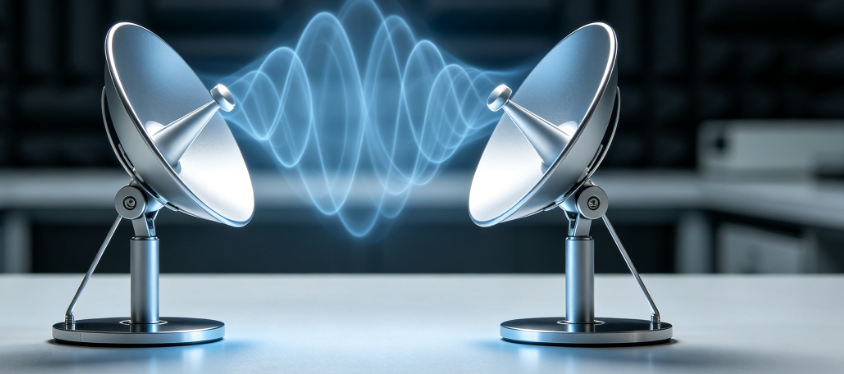
Why Dedicated Microwave Antenna Testing Under Realistic Load Is Essential
Microwave antennas are often modelled as linear, passive networks, but at high power (hundreds of watts to tens of kilowatts), the non-linear behaviour of the feed network, connectors, and the antenna itself becomes significant. Corona discharge, multipaction, and dielectric loss heating can cause the return loss to degrade by 20 dB or more within minutes—yet these effects are invisible in a standard VNA sweep at 0 dBm. Furthermore, when an antenna radiates into a plasma, the plasma's complex permittivity modifies the antenna's input impedance, causing a frequency shift and potential mismatch that reduces power coupling. Our testing protocols are designed to replicate these extreme conditions, providing a complete picture of the antenna's performance envelope from low-power baseline to high-power saturation, and from vacuum to atmospheric pressure. This enables proactive design improvements, safe operating limit determination, and effective troubleshooting of in-service degradation.
Our Core Detection Capabilities for Microwave Generating Antennas
We operate a fully shielded anechoic chamber (10 m × 8 m × 6 m) with broadband absorbing material, coupled to a high-power RF test bench covering 0.5–110 GHz. The following represent our standard high-end offerings:
High-Power S‑Parameter and VSWR Measurements (Up to 50 kW, CW and Pulsed): We employ directional couplers with high directivity (> 40 dB) and custom high-power attenuators to measure the reflection coefficient (Γ) and the forward and reflected power with an accuracy of ±0.02 in magnitude and ±0.2° in phase, at power levels from 1 W to 50 kW (CW) and up to 100 kW (pulsed, 1 µs – 10 ms). We sweep frequency and power to generate a power-dependent S11 matrix, which reveals non-linearities such as impedance shift due to heating or voltage breakdown thresholds. We also perform time-domain reflectometry (TDR) at high power to localise any fault (e.g., connector arcing, cable damage) along the feed line.
Near-Field and Far-Field Radiation Pattern Characterisation at High Power: We use a robotic near-field scanner (measurement area 4 m × 4 m) with a probe antenna that is calibrated to withstand high power levels. The near-field data is transformed to the far-field using a proprietary algorithm, providing gain, directivity, side-lobe levels, and beam pointing accuracy with an uncertainty of ±0.3 dB. We perform these measurements at multiple power levels and at thermal equilibrium (after a 30-minute soak) to capture any pattern distortion due to thermal deformation of the antenna structure. For antennas with integrated ferrite or dielectric components, we also measure the polarisation purity (cross-polar discrimination) as a function of power.
Thermal Imaging and Temperature Distribution Mapping: A high-speed infrared camera (3–5 µm, 640×512 pixels, 0.02 °C sensitivity) is positioned in the chamber to capture the real-time temperature profile of the antenna's radiating surface, feed network, and RF window. We record the temperature rise and the thermal time constant during a step in RF power. This data is correlated with the S‑parameter drift to quantify the thermal detuning coefficient (deg C per MHz). We also perform thermal cycling tests (e.g., 10 cycles from ambient to 100 °C) to evaluate the antenna's mechanical resilience.
High-Voltage Withstand and Multipaction Testing: For antennas used in vacuum or space environments, we perform multipaction testing according to ECSS standards. We apply a swept-power CW signal (from 1 W to rated power) and monitor the reflected power and the higher-order harmonics using a spectrum analyser. A sudden increase in harmonics or reflected power indicates the onset of multipaction. We also perform DC and RF Breakdown Voltage tests using a high-voltage probe and partial discharge detector, providing the safe operating voltage margin.
Plasma-Coupled Antenna Impedance and Radiation Characterisation: For antennas intended to launch power into plasma (e.g., ion cyclotron resonance heating, electron cyclotron resonance), we mount the antenna on a plasma test chamber (with argon or helium, pressure 10⁻³ – 10⁰ Pa) and measure the input impedance and radiation pattern as a function of plasma density (measured by microwave interferometer). We provide the VSWR vs. plasma density curve and the power coupling efficiency (absorbed power / incident power) derived from a matched-load calorimeter. This is critical for ensuring that the antenna remains matched over the full operating range of the plasma source.
Mechanical Vibration and Thermal Shock Testing: We use a shaker table (frequency 5–2000 Hz, acceleration up to 20 g) to simulate launch or operational vibrations, while simultaneously measuring the S‑parameters to detect any intermittent contact or resonance-induced detuning. We also perform thermal shock tests (rapid temperature change from −40 °C to +80 °C) while monitoring the return loss, ensuring that the antenna's mechanical joints and dielectric materials remain stable.
Long-Term High-Power Endurance Test: We subject the antenna to a programmed power profile (e.g., 80% rated power for 1000 hours, with periodic off-cycles) while continuously recording forward/reflected power, temperature, and pattern (via a fixed far-field receiver). Our proprietary algorithm detects gradual degradation (e.g., increasing return loss, decreasing gain) and provides a remaining useful life (RUL) estimate with a confidence interval of ±15%, based on the statistical distribution of historical data.
Integrated Analysis: Correlating Electrical, Thermal, and Mechanical Data
Our unique strength is the simultaneous acquisition and cross-correlation of all diagnostic streams. We use a common clock to synchronise the VNA, thermal camera, vibration sensors, and plasma diagnostics. This allows us to pinpoint, for example, that a 0.5 dB increase in insertion loss at 2.45 GHz is correlated with a 12 °C temperature rise at the dielectric feedthrough, and that this temperature rise coincides with a specific vibration mode (measured by accelerometers). We then apply multi-parameter regression to build a degradation model that links the key performance indicators to the antenna's environmental history. This model is delivered as a dashboard for condition-based monitoring.
We also provide finite-element model (FEM) validation services: we use our measured S‑parameters and thermal data to refine the client's electromagnetic and thermal simulations, ensuring that future designs are accurately predicted.
Our Distinctive Advantages in Microwave Antenna Testing
Our laboratory is equipped with a unique high-power RF source that covers 0.5–40 GHz with up to 10 kW CW (and 50 kW pulsed), combined with a full anechoic chamber and a plasma test cell. We are accredited under ISO 17025 for RF power and antenna parameter measurements, and we maintain traceability to NIST standards. Our team includes RF engineers and plasma physicists with over 20 years of cumulative experience in microwave systems, and we have tested antennas for satellite, fusion, radar, and medical applications.
Our reports are comprehensive and include: - Power-dependent VSWR and return loss (with uncertainty bands). - Radiation patterns (E- and H-plane, co- and cross-pol) at multiple power levels. - Thermal response curves (temperature vs. time and vs. power). - Multipaction threshold and Breakdown Voltage. - Plasma-induced impedance shift (if applicable). - Vibration and shock survivability assessment. - RUL prediction and recommended maintenance intervals.
Typical turnaround for a full characterisation (including electrical, thermal, and mechanical tests) is 8–12 business days, with a preliminary summary within 48 hours. For urgent failure analysis, we offer a 24-hour priority service.
Real-World Impact: Case Highlights from Our Testing
In a recent evaluation of a high-power S-band horn antenna for a radar system, our high-power S‑parameter sweep revealed a sudden increase in return loss at 2.8 kW, which was due to a dielectric breakdown in the coaxial-to-waveguide adapter. The manufacturer had only tested at 500 W and assumed linearity. Our thermal imaging confirmed a local hot spot of 150 °C. After redesigning the adapter with improved cooling, the antenna passed 5 kW CW without degradation, extending its operational margin by 40%.
In another project involving a helicon plasma antenna for space propulsion, our plasma-coupled impedance measurements showed a 16% increase in VSWR when the plasma density exceeded 10¹⁸ m⁻³, causing significant reflected power. We identified that the mismatch was due to a small shift in the antenna's resonant frequency (120 MHz) caused by the plasma's dielectric loading. The client used our data to retune the matching network, increasing power coupling efficiency from 78% to 94%.
Partner with Us for Unmatched Microwave Antenna Performance Assurance
Whether you are developing a high-power antenna for fusion heating, satellite communication, radar, or industrial processing, our detection service delivers the deep, scientifically validated insights you need to ensure robustness, efficiency, and reliability. We welcome customised test plans—from prototype validation to production qualification and field failure analysis. Our experts are available for collaborative troubleshooting and design optimisation.
Let our advanced diagnostics illuminate the true performance of your microwave antennas under the most demanding conditions. Contact us today to design a testing strategy that matches your power and precision requirements.