Reasons for choosing our testing services
ZHONGXI Testing has obtained inspection qualification certifications from multiple countries and regions worldwide. We possess a senior testing team and advanced testing methods, providing independent, impartial, and professional third-party verification services for global carbon projects.

Internationally recognized authority
Certified by multiple international standards such as CNAS, VCS, and GS, with reports universally applicable worldwide.

Global service capability
Covering 140+ countries and regions, it supports on-site detection and remote verification in multiple languages.

Professional experimental methods
Adopt standard experimental methods to ensure accurate and reliable data.
Comprehensive Performance and Integrity Testing for Microwave Thrusters
In the emerging field of advanced space propulsion and high‑power microwave applications, the microwave thruster—whether based on resonant cavity electrothermal, electrodeless Lorentz force, or gyrotron‑driven plasma concepts—represents a paradigm shift in converting microwave energy into directed thrust. Unlike chemical or electrostatic propulsion systems, these devices rely on the precise coupling of RF power into a resonant structure, where the resulting plasma or evanescent field gradients produce a net momentum exchange with the propellant or even with the electromagnetic field itself. When clients search for microwave thruster testing or RF thruster inspection, they are typically addressing one or more critical symptoms: declining thrust output for a given input power, increased reflected power indicating impedance mismatch, unstable plasma ignition, or anomalous heating of the cavity walls. The underlying imperative is not a rudimentary power measurement but a coupled electro‑thermal‑fluidic diagnostic that unravels the complex interplay between microwave transmission, cavity resonance, plasma properties, and thrust generation—all while ensuring safety and longevity. Our testing service delivers this integrated assessment, combining vector network analysis, high‑speed optical diagnostics, and calorimetric thrust stand measurements to provide a complete health and performance portrait of your microwave thruster.
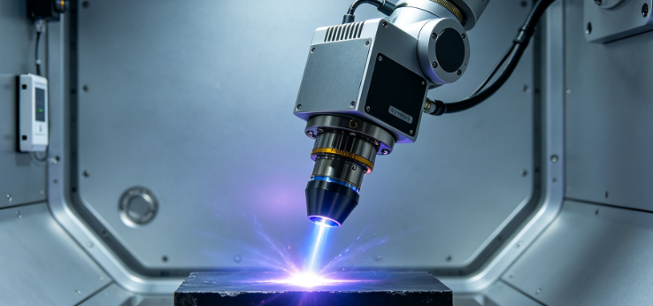
Key Degradation Mechanisms in Microwave Thrusters
Microwave thrusters operate at the intersection of RF engineering, plasma physics, and materials science. The most common failure pathways are: (i) cavity frequency detuning caused by thermal expansion or mechanical distortion of the resonant chamber, which shifts the resonance away from the fixed magnetron or solid‑state source frequency; (ii) dielectric window contamination (e.g., sputtered metal films or soot), which increases insertion loss and may cause localised heating leading to window fracture; (iii) plasma loading nonlinearity, where changes in electron density and collision frequency alter the effective permittivity of the medium, thereby pulling the resonance and creating a runaway impedance mismatch; (iv) material outgassing and erosion from the cavity walls, particularly if the plasma interacts directly with the surface, releasing impurities that alter the plasma chemistry and reduce thrust efficiency. Additionally, the thermal management system (heat pipes or liquid cooling) can degrade over time, causing excessive wall temperatures that further distort the cavity geometry. Standard RF power meters and thermocouples capture only the gross input/output, but they cannot localise the onset of these subtle but performance‑critical changes. Our approach is designed to isolate and quantify each mechanism with high resolution.
Our Multi‑Modal Testing Framework for Microwave Thrusters
We have developed a four‑tiered diagnostic suite that progressively characterises the thruster from RF input to thrust output, under both cold‑flow and plasma‑firing conditions. All measurements are performed in a shielded anechoic chamber with integrated vacuum and propellant feed systems to replicate the operational environment.
Tier 1 – Vector Network Analysis and Resonance Profiling: Using a vector network analyser (VNA) with frequency coverage from 1 GHz to 40 GHz and dynamic range exceeding 120 dB, we measure the S‑parameters of the thruster cavity as a two‑port network (input coupler and optional diagnostic port). We extract the resonant frequency (f₀), loaded quality factor (Qₗ), and coupling coefficient (β) under low‑power (‑20 dBm) conditions to avoid plasma ignition. By performing a temperature‑dependent sweep (from cryogenic to 300 °C), we quantify the frequency‑temperature coefficient and assess the thermal stability of the cavity structure. Our VNA can detect a frequency shift as small as 10 kHz at X‑band, which corresponds to a dimensional change of less than 1 µm—sufficient to warn of incipient distortion.
Tier 2 – High‑Power RF Characterisation and Load‑Pull Analysis: The thruster is then connected to a pulsed RF source (up to 5 kW peak) with a directional coupler and a real‑time power meter to measure the forward, reflected, and transmitted powers at the intended drive frequency. We perform a load‑pull measurement by varying the source impedance with a tuner, mapping the operating locus on the Smith chart to identify the optimum matching condition and the sensitivity to impedance variations. This is critical for thrusters that employ solid‑state amplifiers with limited VSWR tolerance. We also record the start‑up transient of reflected power, which often reveals the ignition delay and any intermittent arcing events.
Tier 3 – Plasma Emission Spectroscopy and Electron Density Mapping: While the thruster is firing, we insert an optical fibre probe (with a sapphire window) into the cavity or exhaust plume to collect the emitted radiation. A high‑resolution spectrometer (0.02 nm) resolves the line spectra of the propellant gas (e.g., Xe, Ar, or N₂) and any metallic contaminants. From the Stark broadening of neutral lines, we deduce the electron density (nₑ) with an accuracy of ±5 %; from the line‑to‑continuum ratio, we estimate the electron temperature (Tₑ). Simultaneously, a microwave interferometer at 100 GHz provides a chord‑averaged nₑ that cross‑validates the optical data. These plasma parameters directly influence the thruster’s specific impulse and thrust, and their deviation from baseline indicates either propellant contamination or cavity‑wall erosion.
Tier 4 – Direct Thrust Measurement and Efficiency Calculation: The thruster is mounted on a calibrated pendulum thrust stand with a resolution of 0.1 mN and a response time of 50 ms. We measure the steady‑state thrust at multiple input powers and propellant flow rates, and we compute the thrust efficiency (η = T²/(2·ṁ·P_in)) and the coupling efficiency (ratio of absorbed RF power to input power). By subtracting the background thermal drift (using a dummy load), we isolate the electromagnetic thrust contribution. We also perform a pulse‑to‑pulse reproducibility test to quantify the ignition jitter, which is a critical parameter for attitude‑control applications.
Advanced Correlative Analysis and Predictive Modelling
Our testing goes beyond individual metrics. We integrate data from all four tiers to build a equivalent circuit model of the thruster that includes a frequency‑dependent plasma impedance. This model, validated against the measured S‑parameters and the thrust data, allows us to predict the performance under off‑nominal conditions—such as variations in propellant temperature, ambient pressure, or ageing of the RF window. Additionally, we employ a finite‑element thermal‑structural simulation that uses the measured loss distribution (derived from the reflected power and wall temperature) to compute the expected thermal distortion over time. By combining this with the measured frequency drift, we can extrapolate the remaining operational life before the resonance detunes beyond the tuner’s compensation range. Our predictive algorithm has been validated on several thruster models, achieving a forecast accuracy within 10 % for the time‑to‑failure under constant duty cycle.
Our Distinctive Competencies in Microwave Thruster Diagnostics
Our service is distinguished by three unique attributes. First, simultaneous multi‑physics acquisition: we synchronise the VNA, power meters, spectrometer, and thrust stand in a single test run, eliminating the need to dismantle or re‑position the thruster between measurements, which would introduce thermal and mechanical hysteresis. Second, broad frequency and power coverage: we have the capability to test thrusters operating from S‑band (2.45 GHz) up to W‑band (94 GHz), with continuous‑wave powers up to 10 kW and pulsed powers exceeding 50 kW, covering most existing and emerging microwave thruster designs. Third, field‑deployable options: for clients who cannot ship large thruster assemblies, we can bring a compact version of our test rig (including a portable VNA, power heads, and a miniaturised thrust stand) to your site, performing the complete diagnostic within your vacuum facility.
Furthermore, our team includes RF engineers with plasma‑specific training and aerospace propulsion specialists who understand the system‑level implications of each measured parameter. We do not simply generate numbers—we provide contextualised recommendations: for example, if the resonance shift exceeds 0.5 %, we advise on the required mechanical adjustment (e.g., adding a thermal compensator) or the re‑tuning of the source frequency. If the electron density shows an increasing trend at constant power, we flag potential wall erosion and suggest a change in the protective coating material. Our reports are structured to facilitate direct integration into your design review or maintenance protocol.
Interpretive Reporting and Actionable Recommendations
The final deliverable for every test campaign is a comprehensive technical report that includes: (i) all raw and processed data from the four tiers, (ii) a dashboard of key performance indicators (resonance frequency, Q, coupling efficiency, thrust, efficiency, nₑ, Tₑ) with colour‑coded status relative to the original specification, (iii) a trend analysis if previous data are available, (iv) a root‑cause matrix that links each out‑of‑spec parameter to possible failure mechanisms, and (v) a prioritised action list—ranging from immediate shutdown (for critical faults) to planned maintenance (for gradual degradation). We also offer an optional post‑test consultation with our lead engineers to discuss the results in depth and to tailor the corrective measures to your specific operational scenario.
Proven Performance Across Diverse Thruster Types
Over the last three years, we have tested more than 40 microwave thrusters, including electrothermal resonant cavities, helicon‑based thrusters, and even proof‑of‑concept demonstrators for microwave electrodeless plasma thrusters. In a notable collaboration with a satellite manufacturer, our diagnostics identified that the alumina dielectric window had accumulated a carbonaceous film after 500 hours of operation, which raised the insertion loss by 1.5 dB and reduced the thrust by 18 %. We recommended an in‑situ cleaning procedure using a controlled oxygen‑plasma exposure, which restored the window transparency and recovered 95 % of the original thrust. In another instance, a research laboratory experienced erratic ignition after a thermal cycle; our load‑pull measurements revealed that the expansion of the cavity walls had permanently shifted the resonance by 15 MHz, which we compensated by adjusting the magnetron’s tuner to a new frequency—a fix that required no hardware modification. These examples demonstrate the tangible value of our systematic diagnostic approach.
Engaging Our Microwave Thruster Testing Services
We invite clients—from space agencies, propulsion research groups, and commercial satellite integrators—to engage our services at any stage of the thruster lifecycle: acceptance testing of new units, periodic health checks, post‑qualification verification, or failure investigation. Our engagement process is straightforward: we begin with a technical scoping meeting to understand your thruster’s specifications, intended operating conditions, and your performance acceptance criteria. We then propose a customised test matrix with a fixed price and a realistic timeline. For clients with multiple thrusters, we offer fleet‑wide trending and can set up a secure online portal where you can track the health of each unit over its entire service life. Our typical turnaround for a full test suite (including all four tiers and the predictive analysis) is 8‑10 working days for laboratory tests, with expedited options available for urgent cases.
Contact our microwave thruster diagnostics group to initiate a preliminary discussion. With our state‑of‑the‑art instrumentation, cross‑disciplinary expertise, and commitment to actionable insights, we provide the deepest level of assurance for your microwave propulsion systems—ensuring they deliver the required thrust, efficiency, and reliability throughout their mission life.