Reasons for choosing our testing services
ZHONGXI Testing has obtained inspection qualification certifications from multiple countries and regions worldwide. We possess a senior testing team and advanced testing methods, providing independent, impartial, and professional third-party verification services for global carbon projects.
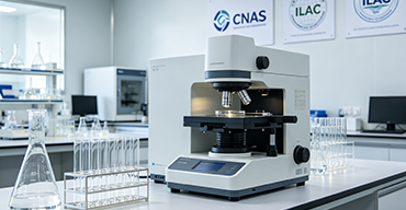
Internationally recognized authority
Certified by multiple international standards such as CNAS, VCS, and GS, with reports universally applicable worldwide.

Global service capability
Covering 140+ countries and regions, it supports on-site detection and remote verification in multiple languages.
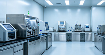
Professional experimental methods
Adopt standard experimental methods to ensure accurate and reliable data.
Advanced Diagnostic Testing of Plasma Beam Splitters: From Optical Performance to Plasma‑Induced Degradation
Plasma beam splitters are critical components in advanced plasma systems, including high‑power laser–plasma interaction chambers, plasma diagnostic ports, and multi‑beam plasma processing tools. These devices are designed to divide an incident plasma flux—or a combination of plasma and optical radiation—into multiple spatially separated beams while maintaining the original beam’s spectral, angular, and energy distributions. Their performance directly impacts the uniformity of plasma treatment, the fidelity of spectroscopic measurements, and the longevity of downstream optical elements. Clients seeking plasma beam splitter testing typically face challenges such as non‑uniform splitting ratios, spectral distortion due to plasma‑induced coating degradation, thermal stress fractures, or contamination by sputtered material. Our laboratory offers a fully integrated, multi‑modal characterisation platform that covers every critical aspect of beam splitter behaviour—from its pristine optical and geometrical parameters to its response under prolonged exposure to reactive plasma environments. We combine high‑precision optical metrology, plasma–material interaction analysis, thermal imaging, and accelerated endurance testing to deliver a comprehensive diagnostic fingerprint that enables predictive maintenance, design validation, and process optimisation.
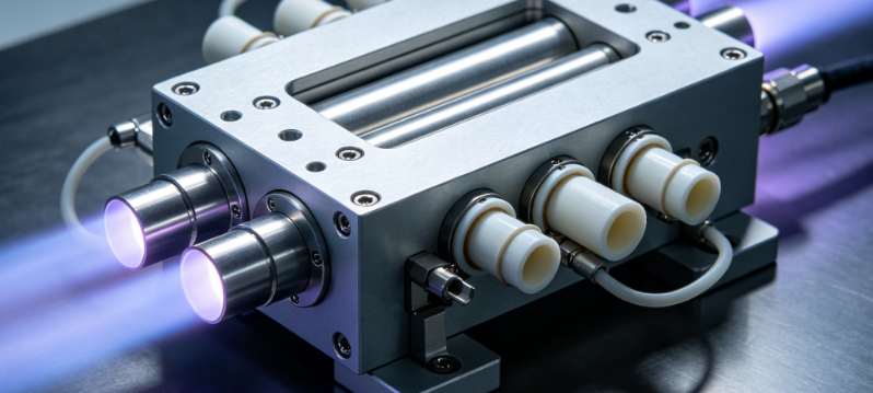
Optical and Spectral Characterisation of the Splitting Performance
The primary function of a plasma beam splitter is to divide the incoming beam with a specified ratio (e.g., 50:50, 70:30) across a defined wavelength range, typically spanning from deep ultraviolet (DUV) to near‑infrared (NIR). We employ a custom‑built spectrophotometric bench that integrates a supercontinuum laser source (190–2500 nm), a motorised goniometer for angle‑resolved measurements, and a high‑dynamic‑range array spectrometer to measure the transmission and reflection coefficients for each output beam. We quantify the splitting ratio accuracy (deviation from the nominal value), the polarisation dependence (s‑ and p‑polarisation), and the angular dispersion introduced by the splitter. For beam splitters used in plasma diagnostics, we also measure the wavefront distortion using a Shack–Hartmann wavefront sensor, and we quantify the stray light level (veiling glare) using a goniophotometer, ensuring that the split beams preserve their spatial coherence and phase information.
To evaluate the spectral fidelity of the splitter, we perform broadband spectral analysis with a Fourier‑transform spectrometer (resolution 0.1 cm⁻¹) to detect any wavelength‑dependent loss or etalon effects caused by residual coating thickness variations. For beam splitters that incorporate dichroic or rugate filters, we map the cut‑on and cut‑off wavelengths with sub‑nanometre precision. All optical measurements are referenced to NIST‑traceable standards, and we provide a detailed uncertainty budget that accounts for source stability, detector linearity, and environmental fluctuations, ensuring that your splitting specifications are rigorously verified.
Geometrical and Surface Integrity Assessment
The physical geometry of the beam splitter—substrate flatness, parallelism, wedge angle, and surface roughness—directly influences the beam divergence and wavefront quality. We use phase‑shifting interferometry (PSI) to measure the surface figure (peak‑to‑valley and RMS) over the full clear aperture, with a precision of λ/20 (at 632.8 nm). The surface roughness (Ra, Rq) is quantified using white‑light interferometry and atomic force microscopy (AFM) on representative areas, detecting any scratches, digs, or coating defects that may cause scattering or hot spots. We also measure the substrate thickness uniformity and parallelism using a precision coordinate measuring machine (CMM) with a touch‑trigger probe, ensuring that the splitter mounts correctly in the optical train.
For beam splitters that include a metal or dielectric coating (e.g., Ag, Au, Al, or multi‑layer dielectrics), we perform coating adhesion testing via a scotch tape pull‑test (ASTM D3359) and abrasion resistance using a Taber abraser, simulating the handling and cleaning cycles that the splitter may undergo in the field. Our 3‑D digital microscopy provides high‑magnification inspection of the coating edges and any pinhole formation, which is critical for preventing plasma‑induced damage propagation.
Plasma‑Induced Thermal and Thermo‑Mechanical Stress Testing
When exposed to a plasma flux—especially in high‑power laser–plasma or plasma processing chambers—the beam splitter can absorb a fraction of the incident energy, leading to temperature rise, thermal expansion, and potential fracture. We mount the splitter in a vacuum chamber equipped with a plasma source (RF or microwave, up to 5 kW) and perform in‑situ thermal monitoring using a high‑speed infrared camera (25‑Hz frame rate, 0.05 °C sensitivity) and embedded thin‑film thermocouples on the substrate edge. We measure the steady‑state temperature distribution and the thermal time constant under various plasma powers and duty cycles. Concurrently, we use a laser Doppler vibrometer to detect any vibration or resonant mode excitation caused by plasma pressure fluctuations, which could misalign the beam paths.
To assess the thermal shock resistance, we subject the splitter to rapid plasma pulsing (on/off cycles with a rise time < 100 ms) while monitoring the transient wavefront distortion with a high‑speed Shack–Hartmann sensor. We also perform accelerated thermal cycling (‑40 °C to +150 °C, 500 cycles) in a controlled environment, followed by re‑measurement of the optical and geometrical parameters. Our finite‑element analysis (FEA) correlation service compares the experimental temperature maps with simulations to predict the critical heat flux that would cause delamination or fracture, providing a safe operating envelope for your specific application.
Plasma‑Material Interaction and Coating Degradation Analysis
Reactive species in the plasma—ions, radicals, and high‑energy photons—can chemically alter the beam splitter’s coating, reducing its reflectance or transmittance and introducing absorption bands. We expose the splitter to realistic plasma environments (gas mixtures: Ar, O₂, N₂, CF₄, etc.; pressures: 10⁻³ to 10 mbar; powers: 100 W to 5 kW) for durations ranging from hours to weeks. At regular intervals, we extract the splitter and perform X‑ray photoelectron spectroscopy (XPS) and time‑of‑flight secondary ion mass spectrometry (ToF‑SIMS) to detect chemical changes (oxidation, nitridation, carbon contamination) on the coating surface and at the interface. We also measure the optical absorption (by photothermal common‑path interferometry) and the surface resistivity (to detect conductive path formation) before and after exposure.
Our post‑exposure spectroscopic ellipsometry (190–1700 nm, variable angle) models the coating thickness and optical constants (n, k) to quantify any erosion or deposition. For coatings that show degradation, we employ transmission electron microscopy (TEM) on FIB‑prepared cross‑sections to visualise the morphological changes—such as void formation, columnar structure alteration, or recrystallisation—which are correlated with the optical performance loss. This comprehensive material‑level characterisation allows us to recommend alternative coating materials or protective capping layers for enhanced plasma resistance.
Long‑Term Stability and Lifetime Prediction
For beam splitters deployed in continuous or pulsed plasma systems, long‑term stability is paramount. We conduct extended endurance tests (up to 3000 hours) under representative conditions, with periodic (every 100 hours) re‑measurement of the splitting ratio, wavefront error, and surface contamination. We apply Weibull statistical analysis to the degradation data to estimate the mean time to failure (MTTF) and to identify the dominant wear‑out mechanism. Our accelerated ageing models (based on Arrhenius or power‑law kinetics) enable you to predict the service life under different power levels and duty cycles, facilitating proactive replacement scheduling.
We also perform environmental stability tests—humidity cycling (10–90 % RH) and salt fog exposure (ASTM B117)—to simulate storage and transport conditions, ensuring that the splitter maintains its specification outside the plasma chamber. Our final report includes a lifecycle cost analysis that compares the cost of re‑coating versus replacement, helping you make economically sound maintenance decisions.
Non‑Destructive Evaluation for Hidden Defects
To complement destructive testing, we offer advanced NDE techniques for pre‑qualification and failure analysis. X‑ray computed tomography (µ‑CT) with a micro‑focus source (voxel size down to 2 µm) provides 3‑D visualisation of internal voids, inclusions, or delamination within the substrate or coating. For surface‑breaking cracks, we use dye penetrant inspection (fluorescent, Type I) and eddy current testing (for conductive coatings). Our acoustic microscopy (SAM) with high‑frequency transducers (50–100 MHz) detects sub‑surface debonding and porosity, offering a C‑scan image that maps the adhesion quality across the entire aperture. All NDE results are overlaid on the optical performance maps to correlate defect locations with any observed beam anomalies.
Customised Test Fixtures and Operational Emulation
We recognise that plasma beam splitters vary in size (from 10 mm to 300 mm diameter), substrate material (fused silica, CaF₂, ZnSe, or silicon), and mounting configurations. Our test chambers are equipped with interchangeable kinematic mounts, windowed vacuum ports, and precision rotation stages to accommodate different beam angles and polarisations. We can replicate your exact plasma source (inductively coupled, capacitively coupled, or microwave) and integrate it with the optical diagnostics, providing an end‑to‑end validation of the splitter’s performance in its actual operating context. We also offer on‑site installation support and alignment verification using our portable interferometer.
For R&D clients, we provide parametric optimisation studies that vary the coating design, substrate material, or mounting stress, while measuring the resulting splitting performance and plasma resistance. Our comparative benchmarking service tests your splitter against competitor products under identical conditions, delivering unbiased data for procurement or technology selection.
Standards, Accreditation, and Scientific Rigour
Our laboratory is accredited under ISO/IEC 17025 for optical, dimensional, and temperature measurements. We follow international standards including ISO 10110 (optical component specification), ASTM E2218 (wavefront measurement), and MIL‑PRF‑13830 (surface quality). All our reference instruments are calibrated by NIST‑accredited providers, and we maintain a comprehensive quality management system that ensures traceability and reproducibility. Our test reports include a full measurement uncertainty analysis and a clear executive summary, making them suitable for regulatory submissions or internal quality audits.
Our Distinctive Expertise and Added Value
What sets our plasma beam splitter testing service apart is the synergistic integration of optical metrology, plasma engineering, and materials science. We do not merely measure the splitting ratio; we interpret the data in the context of your specific plasma environment, explaining how a slight change in coating stoichiometry or substrate curvature could lead to a measurable degradation in splitting uniformity. Our team includes PhD‑level scientists with decades of experience in optical coating design, plasma diagnostics, and failure analysis, enabling us to offer actionable recommendations—such as adopting a protective overcoat, modifying the substrate pre‑treatment, or adjusting the mounting torque—that directly address the root causes of observed issues.
We also maintain a proprietary database of beam splitter performance for various plasma conditions and coating systems, which allows us to benchmark your component against a broad reference population and to highlight areas for potential improvement. Our machine‑learning‑based anomaly detection can flag subtle changes in the wavefront that may not be visible in standard pass/fail tests, providing an early warning of incipient failure.
Furthermore, we offer rapid iteration—tested modifications can be re‑evaluated within 72 hours—and we provide remote data access via a secure portal, so you can monitor your test progress in real time. Our training workshops for your engineering teams on optical alignment and plasma‑compatible handling are also available.
We invite you to schedule a pre‑assessment consultation, where we will define your critical performance parameters and design a customised test plan that balances depth, speed, and cost. With our advanced diagnostic arsenal and deep domain expertise, we transform the complexity of plasma beam splitter behaviour into clear, quantifiable, and optimisable metrics—ensuring that your beam division remains faithful, robust, and durable throughout the lifetime of your plasma system.