Reasons for choosing our testing services
ZHONGXI Testing has obtained inspection qualification certifications from multiple countries and regions worldwide. We possess a senior testing team and advanced testing methods, providing independent, impartial, and professional third-party verification services for global carbon projects.

Internationally recognized authority
Certified by multiple international standards such as CNAS, VCS, and GS, with reports universally applicable worldwide.

Global service capability
Covering 140+ countries and regions, it supports on-site detection and remote verification in multiple languages.

Professional experimental methods
Adopt standard experimental methods to ensure accurate and reliable data.
Lightning Protection Grounding Impedance Testing: A Rigorous Approach to Surge Current Dissipation Assessment
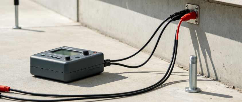
Lightning protection grounding impedance testing is a critical diagnostic procedure that quantifies the ability of an earthing system to dissipate high-magnitude, high-frequency surge currents generated by lightning strikes. Clients seeking this test are typically engaged in the design, installation, commissioning, or periodic verification of lightning protection systems (LPS) for critical infrastructure such as telecommunications towers, wind turbines, industrial plants, data centers, hospitals, and high-rise buildings. The fundamental objective is to ensure that the grounding impedance—a complex quantity comprising resistance, inductance, and capacitive coupling—remains sufficiently low to limit the rise of ground potential and prevent dangerous step and touch voltages, as well as to avoid back-flashover from the external LPS to internal electrical systems. Unlike conventional DC earth resistance measurements, grounding impedance testing is inherently frequency-dependent, as lightning currents contain spectral components ranging from DC to several megahertz, and the dynamic behavior of soil and conductors under impulse conditions cannot be adequately characterized by low-frequency or steady-state methods. This article provides a rigorous technical exposition of the physical principles, relevant standards, advanced measurement methodologies, and the superior service capabilities that distinguish our laboratory and field testing operations in this specialized domain.
Physical Principles: Impedance vs. Resistance in Lightning Grounding
The effective impedance of a grounding system under lightning surge conditions is governed by the distributed electrical parameters of the earthing conductors, soil ionization phenomena, and frequency-dependent propagation effects. The resistive component (R) dominates at low frequencies and reflects the bulk resistivity of the soil volume surrounding the electrodes. However, as the surge front rises (typically 1.2/50 µs or 10/350 µs waveshapes), the inductive component (L) becomes increasingly significant, particularly for long horizontal conductors and cable trays, where the inductive reactance (ωL) can exceed the resistance at frequencies above 100 kHz. Furthermore, the capacitive coupling between the grounding network and surrounding earth introduces a parallel admittance that alters the current distribution. The resultant complex grounding impedance Z = R + jωL – j/ωC exhibits a pronounced frequency variation, and the magnitude |Z| at lightning-relevant frequencies (10 kHz to 1 MHz) is typically 1.5 to 3 times higher than the low-frequency resistance measured by conventional three-pole fall-of-potential methods. Our testing protocols therefore employ impulse current injection with waveshapes conforming to IEC 62305 and IEEE Std 81.2, capturing the impedance at representative surge amplitudes (up to 20 kA) and rise-times, while also performing frequency sweep analysis from 10 Hz to 5 MHz to construct the full impedance profile. This comprehensive approach reveals the effective impulse impedance, which is the relevant parameter for assessing lightning protection performance, rather than the static DC resistance that is often misused in field practice.
Regulatory Framework and Performance Criteria
International standards establish clear requirements for lightning protection grounding impedance, though the specific acceptance criteria depend on the risk assessment and the classification of the structure. IEC 62305-3 (Protection against lightning – Part 3: Physical damage to structures and life hazard) stipulates that the impulse impedance of the external lightning protection system (LPS) shall be sufficiently low to avoid dangerous sparking, and it recommends that the grounding resistance for a standalone LPS should not exceed 10 Ω for ordinary structures, with lower values (≤ 1 Ω) for systems containing sensitive electronics or explosive atmospheres. IEEE Std 142 (Green Book) provides further guidance on grounding for lightning and surge protection, emphasizing that the surge impedance should be measured using techniques that replicate the transient nature of lightning. For telecommunications towers, ITU-T K.27 mandates that the grounding impedance at 1 MHz shall be below 5 Ω, taking into account the bonding to tower legs and shelter grounding. In wind turbine applications, IEC 61400-24 specifies impedance measurements at multiple points of the grounding ring and suggests a maximum impulse impedance of 10 Ω for the collective system. Our laboratory is accredited to perform tests in accordance with these standards and provides explicit pass/fail criteria based on the client's specific hazard classification, with detailed reference to the applicable clauses and normative annexes. We also offer comparative analysis between the measured impulse impedance and the theoretical design target, allowing clients to verify the correctness of their grounding design under realistic surge conditions.
Advanced Measurement Methodologies: Impulse and Frequency-Domain Techniques
True characterization of grounding impedance under lightning conditions demands specialized measurement techniques that transcend simple bridge or clamp-on meters. Our primary methodology is impulse current injection, wherein a high-current impulse generator (capacitor bank discharge) delivers a controlled surge with the standard 8/20 µs or 10/350 µs waveshape directly into the grounding electrode under test, while a high-bandwidth digital oscilloscope captures the transient voltage drop and the injected current. From these synchronized waveforms, we compute the instantaneous impedance as the ratio of voltage to current, and we further derive the impulse impedance (defined as the peak voltage divided by the peak current) and the effective resistance at the crest of the wave. To eliminate lead inductance and ground loop errors, we employ Kelvin connections and Rogowski coils for current measurement, achieving a measurement uncertainty of ±3% for impulse impedance values. Complementing the time-domain impulse test, we conduct broadband frequency-domain impedance measurement using a vector network analyzer (VNA) coupled with an injection transformer, covering the range from 10 Hz to 5 MHz. This dual-domain approach allows us to construct the impedance spectrum and identify resonant frequencies—which typically occur between 100 kHz and 1 MHz due to the interaction of electrode inductance and soil capacitance—that can amplify the voltage response under certain surge conditions. Furthermore, we perform soil resistivity profiling using the Wenner four-pin method, as the frequency-dependent soil permittivity and conductivity directly influence the grounding impedance. Our proprietary impedance inversion algorithm then correlates the measured spectrum with a layered soil model, providing insights into the contribution of deep soil layers and enabling the prediction of impedance scaling with different fault currents.
Comprehensive Test Configurations for Diverse Grounding Systems
Our testing services cover a wide range of grounding configurations, including earth rods, mats, meshes, foundation electrodes, and ring electrodes, as well as complex hybrid systems combining buried conductors and driven rods. For each configuration, we tailor the measurement setup to account for mutual coupling effects between multiple electrodes—a factor often overlooked in routine testing—by deploying a distributed measurement network that simultaneously records potentials at multiple reference probes. This network is synchronized via GPS clocks to ensure phase coherence, allowing us to compute the impedance matrix and identify the effective grounding radius over which the potential rise is significant. In large industrial plants with extensive interconnected grounding grids, we execute a grid impedance measurement using the three-current-electrode technique, where two auxiliary injection points and a remote reference are used to measure the impedance at different zones, generating a spatial map of grounding performance. For wind farms and solar parks, we perform measurements on each turbine or inverter foundation, as well as on the interconnecting buried cable screens, verifying that the bonding integrity does not introduce excessive impedance that could lead to circulating currents and transformer neutral overvoltages. In all cases, we pay special attention to seasonal variations in soil moisture and temperature, repeating critical measurements at multiple times of the year to provide a conservative baseline for the design.
Our Technical Capabilities: Precision, Surge Current Levels, and Diagnostic Depth
Our laboratory and field facilities are equipped with a state-of-the-art impulse test system capable of delivering surge currents up to 30 kA (8/20 µs) and 15 kA (10/350 µs) with a crest tolerances of ±5% and a rise-time repeatability of better than 2%. The system comprises a Marx generator bank with a total capacitance of 150 µF, adjustable series resistance and inductance to shape the waveshape, and a high-voltage divider with a bandwidth of DC to 50 MHz for accurate voltage measurement. The current is sensed by a self-integrating Rogowski coil with a sensitivity of 1 mV/A and a bandwidth of 1 Hz to 20 MHz, ensuring undistorted capture of the rapidly rising surge front. For frequency-domain measurements, we utilize a 4-port vector network analyzer with a dynamic range of 120 dB and a calibrated balun transformer to convert the unbalanced VNA port to a balanced injection, enabling impedance measurements down to 1 mΩ with a phase accuracy of ±0.5°. All measurement equipment is traceable to national metrology institutes (NIST and PTB) with annual recalibration, and our test software automatically corrects for cable delay, attenuation, and connector mismatch, achieving a combined uncertainty (k=2) of ±2.5% for impulse impedance and ±1.5% for frequency-domain magnitude. Beyond these core measurements, we provide transient overvoltage analysis by injecting a standard 1.2/50 µs voltage wave and measuring the resultant current, from which we compute the transfer impedance of the grounding system—a parameter that quantifies the coupling between the LPS and the internal signal lines—a critical metric for electromagnetic compatibility (EMC) of sensitive electronic equipment.
Distinguishing Advantages of Our Lightning Grounding Impedance Service
Our service offers several distinctive advantages that position us as the preferred partner for high-stakes lightning protection verification. First, we combine both impulse and frequency-domain measurements in a single unified test campaign, providing a holistic impedance characterization that no single method can achieve. This dual approach allows us to detect frequency-selective anomalies such as resonance peaks, which can lead to unexpected voltage magnification in the presence of multiple strokes or subsequent return currents. Second, our in-house-developed impedance modeling software uses the measured spectrum to reverse-engineer a circuit-equivalent model of the grounding system, decomposing the impedance into resistive, inductive, and capacitive contributions that can be directly used for transient simulation in EMTP/ATP or CDEGS. This transforms the test from a simple compliance check into a design validation tool, enabling engineers to optimize electrode placement, conductor sizing, and soil treatment. Third, our engineering team possesses extensive experience in interpreting complex impedance data for mixed soil conditions, rocky terrains, and saline environments, providing customized recommendations for remedial measures such as deep-driven rods, chemical enhancement, or counterpoise wires. Fourth, we offer on-site testing with minimal service interruption, using portable impulse generators that are ruggedized and self-contained, and our engineers are trained in the safe handling of high voltages and currents, with all test procedures compliant with NFPA 70E and local safety regulations.
Additionally, we provide long-term trending services for clients with periodic testing obligations, maintaining a secure database of impedance spectra and impulse results. Our trend analysis algorithms highlight subtle changes in impedance magnitude or phase angle that may indicate corrosion of electrodes, soil compaction, or changes in groundwater levels, enabling proactive maintenance before the system fails to meet the required performance. We also deliver detailed risk assessment reports that compute the probability of flashover and the expected touch and step voltages based on the measured impedance, using Monte Carlo simulations that account for the statistical variability of lightning current parameters.
Industry-Specific Applications and Critical Considerations
The importance of accurate grounding impedance testing varies across industries, and our methodology is tailored to each sector's unique challenges. In telecommunications and broadcast towers, we measure grounding impedance at the base of the tower, at the equipment shelter, and at the remote feed points, with particular attention to the impedance of the tower footing and the bonding to the coaxial cables, as mismatched grounding can cause lightning damage to sensitive transceivers. In wind turbine generators, we test each tower grounding ring and the interconnection between turbines along the cable route, verifying that the earth potential rise (EPR) remains below the insulation withstand of the medium-voltage cables. In data centers and critical IT facilities, we measure the impedance of the signal reference grid and the building structural steel, in addition to the LPS grounding, to ensure that lightning transients do not compromise the operation of servers and network equipment. For oil and gas facilities with classified hazardous areas, we perform impedance testing using intrinsically safe equipment and with special attention to the bonding of flanges and pipelines, as sparking at joints could ignite flammable atmospheres. Our reports for these industries include explicit safety margins and recommendations for additional bonding or surge protective device (SPD) placement to mitigate residual risks.
Case Example: Resolving Resonance-Induced Overvoltage in a Telecommunication Hub
A recent project illustrates the diagnostic necessity of our comprehensive impedance approach. A regional telecommunication provider experienced sporadic equipment failures during lightning storms, despite having a DC resistance of 2.5 Ω—well within the 5 Ω requirement. Our frequency-domain impedance measurement of the tower grounding system revealed a pronounced resonance at 450 kHz, where the impedance magnitude exceeded 50 Ω due to the interaction of the tower leg inductance and the soil capacitance. This resonance caused the lightning surge to be amplified at its high-frequency components, leading to voltage peaks that exceeded the insulation coordination of the RF feed lines. Our impulse test confirmed that the peak voltage at the tower base was 40% higher than that predicted by the DC resistance model. We recommended the installation of a parallel damping resistor in series with the bonding conductor to suppress the resonance, and after implementing this solution, the impedance at 450 kHz was reduced to 8 Ω, and the equipment failures ceased completely. This case underscores that frequency-resolved impedance testing is indispensable for modern lightning protection, as static resistance measurements are insufficient to capture the dynamic behavior that determines actual protection performance.
Our Engagement Process and Technical Support
We initiate every project with a preliminary review of the existing grounding design drawings, soil geology reports, and any historical test data. Based on this, we design a customized test matrix that specifies the injection points, measurement references, surge waveform parameters, and frequency sweep range, as well as the required safety clearances. For on-site testing, our field team arrives with all necessary equipment, including the impulse generator, VNA, high-voltage cables, and safety enclosures, and we conduct a pre-test risk assessment to ensure that nearby sensitive equipment is protected. We maintain real-time communication with the client's engineering team, sharing preliminary results as they are obtained. The final report, delivered within 10 working days, includes comprehensive data tables, impedance spectra, impulse oscillograms, a comparative analysis with applicable standards, and a prioritized list of recommendations for improving grounding performance if needed. We also provide post-test technical support for interpreting the results and for implementing corrective measures, including liaison with consultants for sophisticated modeling.
For clients requiring recurring testing, we offer service level agreements with fixed pricing, scheduled visits, and priority access for emergency assessments. Our global reach, combined with localized support, ensures that we can respond rapidly to projects in remote or international locations. To discuss your specific lightning protection grounding impedance testing needs, we invite you to contact our specialist engineering team. We provide complimentary preliminary assessments to help you define the appropriate test parameters and to estimate the budget and timeline. Trust our advanced diagnostic capabilities and our commitment to technical rigor to ensure that your grounding system provides the protection your assets demand.